The configuration is a set of parameters that are given to the simulation engine (Exec). You can, in a same project, create several configuration that represent several situations. For opening a configuration document, double click on the node that gives the name of the configuration from the simulation tree (Project explorer). The active configuration is the one that is 'bold' in the tree.
You can use the 'Create shortcut' button for creating a shortcut, on you desktop for exemple, that quick-run the simulation engine according to the open configuration parameters.
Physics parameters
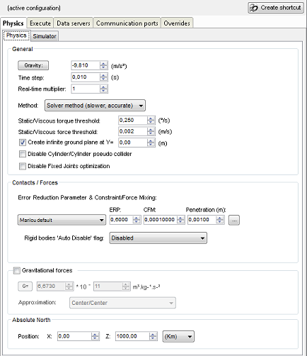
- Real-time multiplier: multiplication factor for the simulator's time base (runs the simulation at real time * Real-time Multiplier factor).
- Create infinite ground plane: indicates if an infinite plane must be created by the simulator at the specified Y position.
- Disable Cylinder/Cylinder pseudo collider: as ODE does not manage cylinder vs cylinder collisions, Marilou is using the capsule vs capsule collider for cylinders. That's mean that cylinders flat sides are considered like spheres. When cylinders are near, flat sides spheres can collide and 'eject' cylinders with big forces.
- Contact/Forces: ERP (Errors reduction parameter) is the error quantity to be reduced every time step. CFM (Constrain force mixing) can be represented as the world elasticity. For a very rigid world, use ERP near 1 and CFM near 10-5. For an 'Elastic' world, use ERP near 0.1 and CFM near 1.0 (See ODE documentation for more details). You can also choose to compute these values automatically from a spring constants by pressing the ... button. The automatically computed values are according to the Time Step value: if you change the Time Step, you must re-compute the ERP/CFM.
- Rigid Bodies 'Auto Disable' flag: Auto Disable feature can be enabled/disabled here. If you choose to enable it, you have to change the ERP/CFM/Penetration values (stability) : the most important is to disallow Interpenetration that are more greater than 0.0001 m.
- Gravity: sets the value for the gravity vector in the world.
- Time step: time increment between two iterations of the physics motor, expressed in simulated seconds. Larger time increments lead to less stable physics simulation, but also require less CPU consumption. On the other hand, shorter time increments result in stable simulation, but higher CPU consumption. The default value is 0.01s (10ms), offering the best ratio of simulation quality/CPU consumption. Digital errors are least significant when using values 0.001, 0.002, 0.004, 0.005 or 0.01.
- Method: indicates the algorithm for the physics motor to use during simulation. The "Solver" method is more accurate than the "Iterative" method, but it is also slower.
- Static/Viscous torque threshold: Static/Viscous torques management: if the axis rotation speed is less than or equals to the threshold, the static torque is applied to the axis. Otherwise (speed > threshold), the viscous torque is applied. In the reality, the threshold = 0: in simulation, it must be set according to the simulation granularity (time step).
- Gravitational forces: Allow gravitational forces management: it is possible to set the gravitational constant G and the forces generation approximation system. The fastest method is the Center/Center one because entities are not subdivided and force is computed and applied from centers to centers. Subdivide XX methods subdivide geometries along their greater length. Then, forces are calculated from each sub-center to each sub-center. The complexity of the system is (Number of geometries * Number of geometries) * (XX * XX). (where XX = 1 for the method Center / Center). G value is set entering the constant value (V) then the exponent (P). The result is : V*10e(-P).
- Absolute North: north pole position : used by the AbsoluteCompass device.
The G and Gravity buttons restore the default values.
Simulator parameters
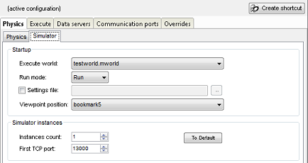
- Execute world: associates a world with the current configuration : this is the world (*.mworld) to be load on the simulation start.
- Run mode: indicates whether or not you wish the simulation to start running immediately or in "pause" mode.
- EXEC settings file: forces Exec to start with a predefined settings file.
- Viewpoint position: user viewpoint position on simulation startup (See also Bookmark).
- Instances count: number of simulator instances to start on the local machine. Each instance is run in its own window.
- First TCP port: the TCP port of the first Exec instance. The next instance is using First TCP port+1 etc.
Execute
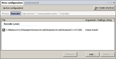
Programs list to be run on simulation startup. Check/uncheck the full path line to allow/disallow the automatic run.
The application's command line is automatically completed by Exec (on application startup).
Data Servers
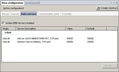
Some of the compatibility plug-ins used for robots (PHX Configuration) need to be informed which TCP or COM port to connect to. The Data Servers tab tells the configuration about all the plug-ins that have declared a variable that needs to be filled in. For example, if several robots are accessible via a virtual serial port, you must assign a different port number to each one. For example, each Urbi server for LEGO MINDSTORM NXT must be mounted on its own TCP/IP port. In this screen shot, you can see that the configuration detects that the robot "/robot" needs two TCP/IP ports. Values 40000 and 50000 are passed to the plug-ins, which then mount their own servers.
We can summarize this by saying that Data Servers are used to obtain a number (for the TCP or COM port) that will be used by the compatibility plug-in to mount its server. This functionality should not be confused with Data Exchange, described here:
Communication ports
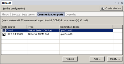
Communication Port is used to create bridge between 'real world' side and simulated device side (TCP server). The port reads and writes data from/to the selected device. (See also External Communication plugin).
Overrides
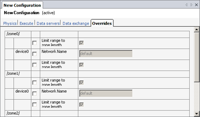
Overrides works like Data Servers, but for overriding variables made available by embedded devices.
Some devices offer options that can (or must) be modified before execution. For example, an 802.11 Wi-Fi access point offers a default network name. If you wish to setup several networks in your simulation, you can either:
- Create devices that use different network names, or
- Use the same device for all networks and override the network name in Overrides. This solution is far more practical to use because you do not have to redefine new devices.
In some cases, Overrides also acts as a functionality collector that allows you to bypass device setup and run tests that would be impossible to reproduce in reality (for example, extending the range of an 802.11 transceiver to 1024 km without changing its configuration).


 Description