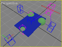
Joints and Zones.
We will connect wheels to the robot's base using joints. Also, we will create the entities (zone) that are allowed toi embed distance sensors. Devices are created in the next chapter.
|
Step |
Description |
|
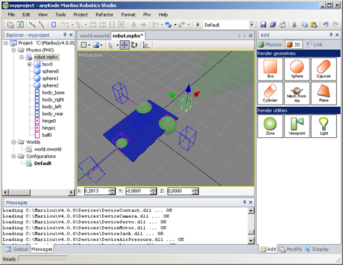
Creating a HINGE joint (1 axe): Joints are created like other geometries.
|
 |
|
Second joint:
|
|
|
Rear joint:
|
 |
|
Move the joints: We have to set joints position in order to make a wheel can turn around joint's axis. For doing that, we just have to set joint's position exactly the same as wheel's position.
|
 |
|
Rename joints:
|
|
We will connect joints and rigid bodies. Wheels will be able to turn around joint axis.
|
Step |
Description |
|
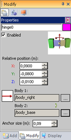
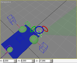
Connecting:
|
 |
|
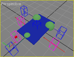
Check: For checking that your joints are attached correctly, you can move it: two lines show the connected bodies. (press Ctrl + Z) for undoing the joint's move ... |
 |
Creating zones and connecting it to the base.
|
Step |
Description |
|
Creating the zone:
|
 |
|
Move the zone and duplicate it:
|
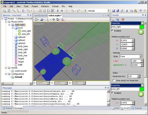 |
|
Note: You can rotate the zone using the Rotate Mode (R):
|
 |
In the previous chapter we explained that the entities would be ejected violently if we run the simulation, due to the interlocking wheels in the base since the start of the simulation. Now, because the rigid bodies are connected Solver will no longer try to resolve any contacts / efforts between the wheels and the base. To override this behavior (which is very useful in our example), just check the property 'Collides with connected bodies' of rigid bodies. Collision detection system (and therefore the calculation of effort) is activated if the option is checked on two rigid bodies in contact.
|
Documentation v4.7 (18/01/2015), Copyright (c) 2015 anyKode. All rights reserved.
|
|
What do you think about this topic? Send feedback!
|


 Description