anyKode Marilou
ContentsIndexHome
PreviousUpNext
Step 1

Dynamics parts.

In this chapter, we will create physics geometries required for robot. We will talk about joints, distance sensors and motors in the next chapters. 


Step 1: Physics part
Step 
Description 
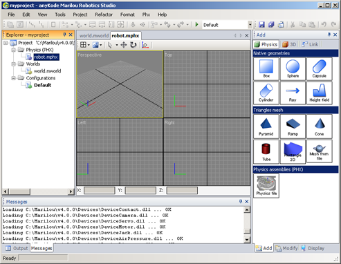
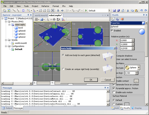
Activate the robot.mphx document:
If robot.mphx is not open, double click on corresponding tree-node from Explorer in order to open the document.

From right panels, choose the Add panel -> physics geometries are shown, we will use it for the robot. 
 
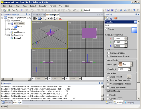
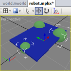
Create de mobile base:

  1. Click on the physics Box geometry for activate the create mode of a Box,
  2. Move mouse cursor over perspective view then start drawing the box,
  3. Choose Select Mode (S) then double-click on the created box for showing its properties inside the Modify panel. (you can directly select the created box then activate the Modify panel manually).


Box physics properties:

  1. Click on Reset Local Matrix button for reset the box's position and rotation,
  2. In box properties, set length (L)=0.3, width (W)=0.2 and height (H)=0.01. (unit is meter).
  3. Set Mass=0.5 Kg.


The box that will be use in collision detection is now centered and have good lengths. 

 
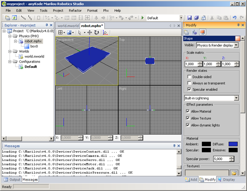
Box display properties:
Click on Shape icon (red screen) for showing box's display properties.

From Material group, click on the Diffuse button and choose for exemple the blue color.

Note that transparency is performed by changing the diffuse color's alpha property. 
 
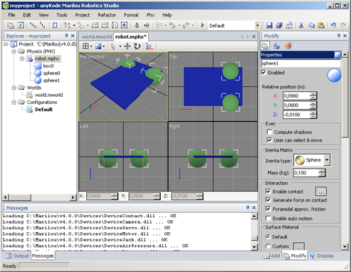
Creating the first wheel:
We will use Sphere for creating wheels because collision detection is faster with this kind of geometries than Cylinders or Capsules (CPU).

  1. Activate the Add panel,
  2. Click on the Sphere for activate the Create Mode,
  3. Create the sphere in the perspective view,
  4. Enter Select Mode (S), and activate the Modify panel,
  5. Change sphere position according to the right screen shot.


Note: You can change position by setting values in Relative Position fields or, using the Move Mode (M) then moving the object with the mouse along object's axes.

Then, set the following values for the sphere:

  • mass = 0.1 Kg
  • ray = 0.045 m


Creating the second wheel:

  1. Set mouse mode to 'Select Mode',
  2. Select the Sphere from a view,
  3. Copy/Paste (Ctrl + C, Ctrl + V)-> a new sphere is created at its clone's position.
  4. Enter Move Mode (M),
  5. Move the mouse cursor along the Y axe (green) and when its color changes to yellow, press left mouse button to capture it. (view must be activated to perform this operation).
  6. Move the mouse along Y+ for moving the new sphere to the left of the robot.


Now, the new sphere is located on the left of the robot, at an approximative position. You can change directly the position from the Modify panel (selecting the sphere before) or use the fast commands Same xxxx:

  1. Select the first created sphere, then the second one (select order is important, use Ctrl key for performing multiple selection),
  2. Press Shift + Y for performing Same Y command (Shift is used to perform Y2=-Y1 instead of Y2=Y1) -> the second sphere's Y position is moving to -Y of the first one !


Rear wheel:

  1. Enter in Select Mode (S),
  2. Select a sphere then Copy/Paste it,
  3. Enter Move Mode (M),
  4. Set is position as shown on the picture (set Y=0 and ray=0.045)


Step 2: Dynamics

Now, geometries are static. We will create dynamics property using Rigid Bodies (Rigid Body geometries). 


In the world, we use the static geometries for creating entities with an infinite mass that is very fast to simulate. For exemple a building, a bridge or a test area. These entities do not need to be dynamic, it is therefore unnecessary for the solver to lose time making a balance of forces on these objects. Note that the static entities are involved in shock with the dynamic entities! 


Step 
Description 
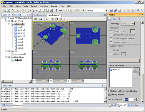
Creating Rigid Bodies:
We will use the automatic method for creating rigid bodies.

  1. Enter in Select Mode, then in a view, press Ctrl + A for selecting all entities,
  2. Click on the Auto rigid Body icon () for starting automatic creating,
  3. Choose option detached for making all entities are dynamics (we don't want a rigid group).


It is also possible to create a rigid body drawing it in a view like others entities. You can find it from the Add-> Link -> Rigid Body panel. After creating it by this way, you can add/remove child from its properties panel. 

 
Adjusting sizes:
You can see that rigid bodies size (which is purely visual and has no effect in the simulation) is not uniform.

  1. Enter in Select Mode (S) and select all rigid bodies (using Ctrl for the multiple selection),
  2. Show the Modify panel,
  3. Set Anchor Size to 0.1 : this change is propagated to all selected entities.


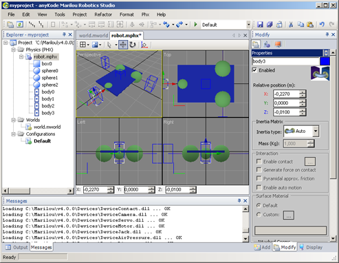
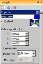
For more comfort for the future, move the rigid bodies in order make them away from the robot. This manipulation does not affect the simulation because rigid bodies are in automatic mode (Inertia type 'Auto').

(See Rigid Bodies properties)
 
 
Rename entities: 

  • Select base rigid body then rename it body_base,
  • Select left wheel rigid body and rename it body_left,
  • Select right wheel rigid body and rename it body_right,
  • Select rear wheel rigid body and rename it body_rear.


If you try to run the simulation with this model, you will see that geometries are ejected ! Indeed, the dynamic entities are in a situation that is not normal because they are in a state of interpenetration. The simulator will have no other choice that to apply massive force to try to separate out from each other.

Documentation v4.7 (18/01/2015), Copyright (c) 2015 anyKode. All rights reserved.
What do you think about this topic? Send feedback!